Mecha Construction - Part 1
Applications: Rhinoceros 3D
Introduction: The Story
In the year 2030 on the distant planet of Vergos 10, natural resources have dropped to an all-time low, and mining operations are forced to go deeper than ever imagined before. Due to the pressure of the inner earth and explosive gasses at severely low depths, miners are not able to enter the bottom of the mines. This called for a new way to mine. Within a short amount of time, mechanical units were assembled to explore and work in the mines. Each Unit is controlled at a station above the surface in a virtual environment where the mechs eyes become yours.
Traits of Vergos 10 Dig Grappler
Lets check the general working conditions and the situations that this machine must endure. With all machinery, it is very heavy and has crushing strength beyond belief. This is a mech, that works in a mine, digging, moving, crushing, and exploding the deep rock and metal within. It must be heavy and strong enough to lift thousands of pounds of material and make quick moves. The eyes in the forehead are also equipped with heavy-duty floodlights that change themselves when they become old. Each mech weighs a minimum of 40,000 pounds (20 tons) and stands 16 feet tall. This machine will need large claws to move objects, as well as a jack hammer-type tool to break objects apart. Large feet should be made to make this heavy mech stable
Concept Sketches
Concept sketches are very important. They let you plan your creature or object out before modeling. This makes the whole process much quicker than before. You are not limited to what is in your concept sketch, and you may go back and change it later. Many times you will create a few concept sketches and then combine certain things to plan out what you want. All in all, concept sketches are worth the time to make them. In Figure.1 you can view the concept for the Vergos 10 Dig Grappler.
Figure.1
Vergos 10 concept sketch
Modeling in Rhinoceros
Here is where most if not all of the work in this tutorial will take place. You will be making maps outside of Rhino to use but basically you will use only Rhinoceros to model the Vergos 10 Dig Grappler. In this tutorial you will use a wide range of tools. Ranging from Loft, 2 Rail Sweeps, to pipes and patches. You will use an adequate amount of tools in Rhinoceros to model this mech, and it will benefit you dearly to check out what each one does exactly in your user manual. This tutorial does not give all of the situations that these tools can be used in. Figure.2 shows all buttons used in this tutorial.
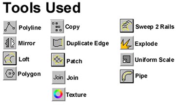
Figure.2
Modeling the Torso
To start the model we will begin with the torso by lofting splines. The type of splines that we use will be polylines. We will use polylines because they have a straight rigid edge that we want for our mech. It is quite hard to get an interpolated spline to look straight with sharp edges. The major downfall of using polylines is that they are un-editable once lofted. It will make a polysurface, which at this point in time, Rhino has, no point or CV editing capabilities for. Figure.3 shows a set of polylines drawn in Rhinoceros.
Figure.3
I have used the right and front viewports to draw these. You can use the command Polyline to access this tool. One these 5 splines are drawn you can mirror the middle front spline by using the Mirror command. Figure.4 shows the process of mirroring the splines.
Figure.4
You will have to click where you need the pivot to be. The pivot in this case is at the center of all the splines. Figure.5 shows the aftermath of mirroring twice, once for each side.
Figure.5
Now that you have all of the splines drawn you can now choose a method of building a surface. There are several ways to do this but for what we have done so far in this situation it would be best to use the loft tool. To access the loft command simply type Loft into the command line and press Enter. You can either have all of your splines selected before entering this command, or select them after entering the command. Once your splines are selected press enter and you should see a loft dialog box pop up. Figure.6 shows the settings that have been used in this case. Below are some explanations on what the settings do in the loft dialog.
Figure.6
The terms and buttons of the Loft dialog box
After completing the loft you should have a renderable surface for the torso. Now we can go model the lower body.
Lower body
Figure.7 shows the polylines drawn for the lower body.
Figure.7
The front and back polylines need to now be mirrored just as you did for the upper body. In Figure.8 you will see the newly mirrored polylines along with the old ones.
Figure.8
The mirrored polylines are in yellow to separate them from the father splines. You can now Loft as you did on the upper torso. Figure.9 shows the output of the loft.
Figure.9