Mecha Construction - Part 4
Applications: Rhinoceros 3D
The Head
As with anything, you could do a multitude of different things with the head. Many people prefer a sleek design, and some prefer a more boxy shape. We will do one of each. First, we will start with a sleek, bullet-shaped head. In Figure.37, you can see the splines drawn for the head. These are interpolated curves.
Figure.37
You use interpolated curves because they define smoothness where polylines do not. Splines of the same color are the same, just mirrored.
It would now be smart to zoom into the top poles of the head splines and check to see if they all come together exactly at the same point. This is important, because if they do not, you will see either a small hole or a twisted spot on the surface. Figure.38 shows the splines at the upper poles before editting.
Figure.38
You can turn on points by using the command ShowCV. The easiest way to get points to be in a certain area is to use object or point snaps. For this surface, we will use point snaps. You can turn on point snaps by clicking osnap button at the bottom of the application, as seen in Figure.39. This figure also shows the check at the point snap.
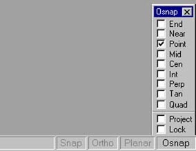
Figure.39
This will make points snap at another point exactly. Figure.40 shows the effect of point snap. You will notice a big difference in the loft compared to the result if you didnt use Point Snaps.

Figure.40
Now loft the surface as a closed normal loft. You should get a product similar to Figure.41. You can place this in position as a dome where the head would go.
Figure.41
The boxy head will also use object (point) snaps and will be modeled by lofting a set of splines as we have done so many times before. This head will be started with all polylines. Figure.42 shows the polylines used and mirrored. Once mirrored, you can build the surface using a closed, straight section loft.
Figure.42
For the eyes, we will use a set of polygons (splines). Figure.43 shows the polygons. The smaller set is scaled down a bit. To scale them, select the splines and use the command Scale.
Figure.43
Now you can click and drag to your size. Use a open, straight section loft. Once lofted, you will need to patch the edge splines. (If you deleted your edge splines, you will need to redraw them to the exact size once again). Use patch with the settings that were used previously in this tutorial. You have to do this for each side. Once finished, you can now join the three surfaces using the Join command.
In Figure.44, you will see how the eyes have been positioned. You can rotate objects using the Rotate command.
Figure.44
Figure.45 shows the total model as we have done so far. We are almost finished. The parts left are some wires and other small details that make a difference.
Figure.45
Small details that make a difference
Small details can make a major difference in the way people look at your models and renders. In Figure.46, you can see a close up of the arm area with a interpolated spline. This will be used as a wire or cable near its arm region.
Figure.46
You can make a solid surface out of this using the Pipe tool. Access this tool by typing Pipe into the command line and pressing Enter. At the prompt for a pipe size, you can either enter a keyboard command such as a size in numbers (we have used .07 as a radius), or you can draw the radius when the size prompt is shown in the command line.
Now that the wire has been finished, it must connect to something, so we will make an input for it to connect to. Figure.47 shows the polygon splines used in creating the input surface.
Figure.47
Use a normal, closed loft to get the surface, as seen in Figure.48. Small details such as these make a big difference in the reality of a character.
Figure.48
There are of course many more small details that could be added, but that would make this tutorial endless.
Surfacing
Rhinoceros 3D 1.0 does not support many surfacing features. For this reason, it would be wisest to surface your mech or any other creature or object in a separate application. With the release of 2.0, an open plugin interface is said to be on the list of new features to be introduced. With this may come some very interesting options.
Rhinoceros does, however, offer the use of Texture and bump maps, as well as transparency and highlight. These options are quite limited. If you need high quality renders, use applications such as 3D Studio Max, Maya, or Lightwave. There are also many more stand-alone renders such as Pov-Ray or BMRT. Get Pov-Ray at www.povray.org for free. In Figure.49, you can see the final completed model.
Figure.49
Wrapping this up
Well, with this tutorial coming to a close, you can see how easy it is to model a mechanical character in Rhinoceros 3D. While modeling this character, you went over many of the tools available in Rhinoceros 3D 1.0. Working in Rhinoceros takes time and practice as with any application or anything in life in general. Keep modeling and be patient, because to some there is no greater reward or feeling than creating great computer graphics. If youre not there already, then some day you will be. Keep your patience and keep modeling in Rhinoceros.